

How To Draw Beam And Column Layout
Your guide to SkyCiv software - tutorials, how-to guides and technical articles
Beam, Column Design – S3D
Designing Reinforced Concrete Sections from within SkyCiv Structural 3D Assay Software
SkyCiv Reinforced Concrete Design Software allows engineers to pattern concrete beams and columns as per ACI 318, AS 3600, EN two, CSA A23 and BS 8110 (coming before long). The software is available as Standalone (no analysis), or integrated with our assay software; SkyCiv Beam and SkyCiv Structural 3D. In this commodity, we will explore the usage of RC blueprint from within SkyCiv Structural 3D (S3D):
Modelling your Structure
The integrated RC design module allows users to model their construction and apply loads and load combinations using our Structural 3D program. This volition allow the user to (a) model, analyze and design multiple members at once (b) perform more complex and accurate analysis on the members (c) automatically import attributes such as length and section properties from the model -> RC design module.
For more data on how to model using S3D – visit our getting started in S3D folio.
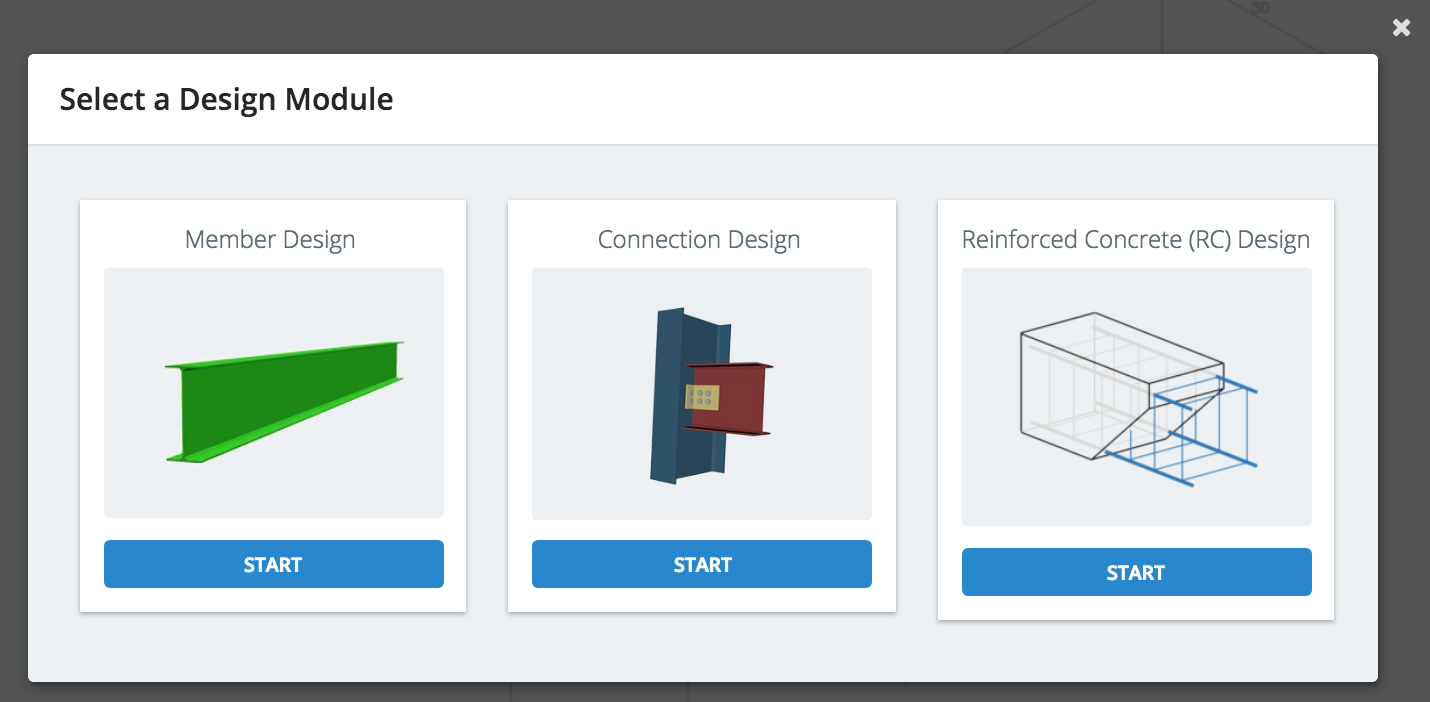
Open the Design Module
Once you have solved the structure, you lot tin can open the design module for your particular design code. To do this, visit theDesignbubble in the acme right corner and launch the design module of your choice:
The following information will automatically be imported into the design module:
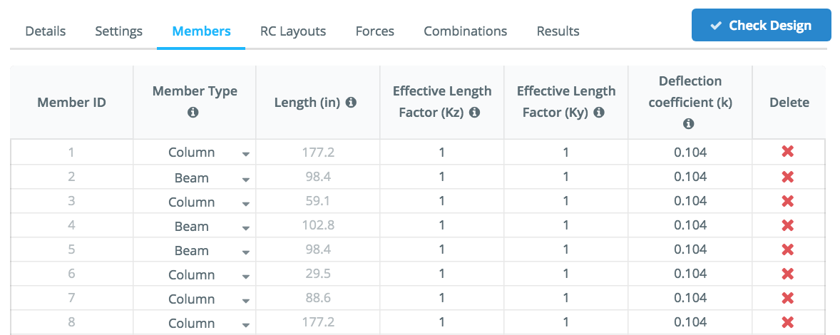
Members
All of your members will automatically be imported from the assay model. This includes an auto-assign of whether your members should be classed as beams/columns as well equally lengths and effective length factors. Annotation: Yous can edit and control any of these options at any time and your changes will be saved with your model (File – Save).
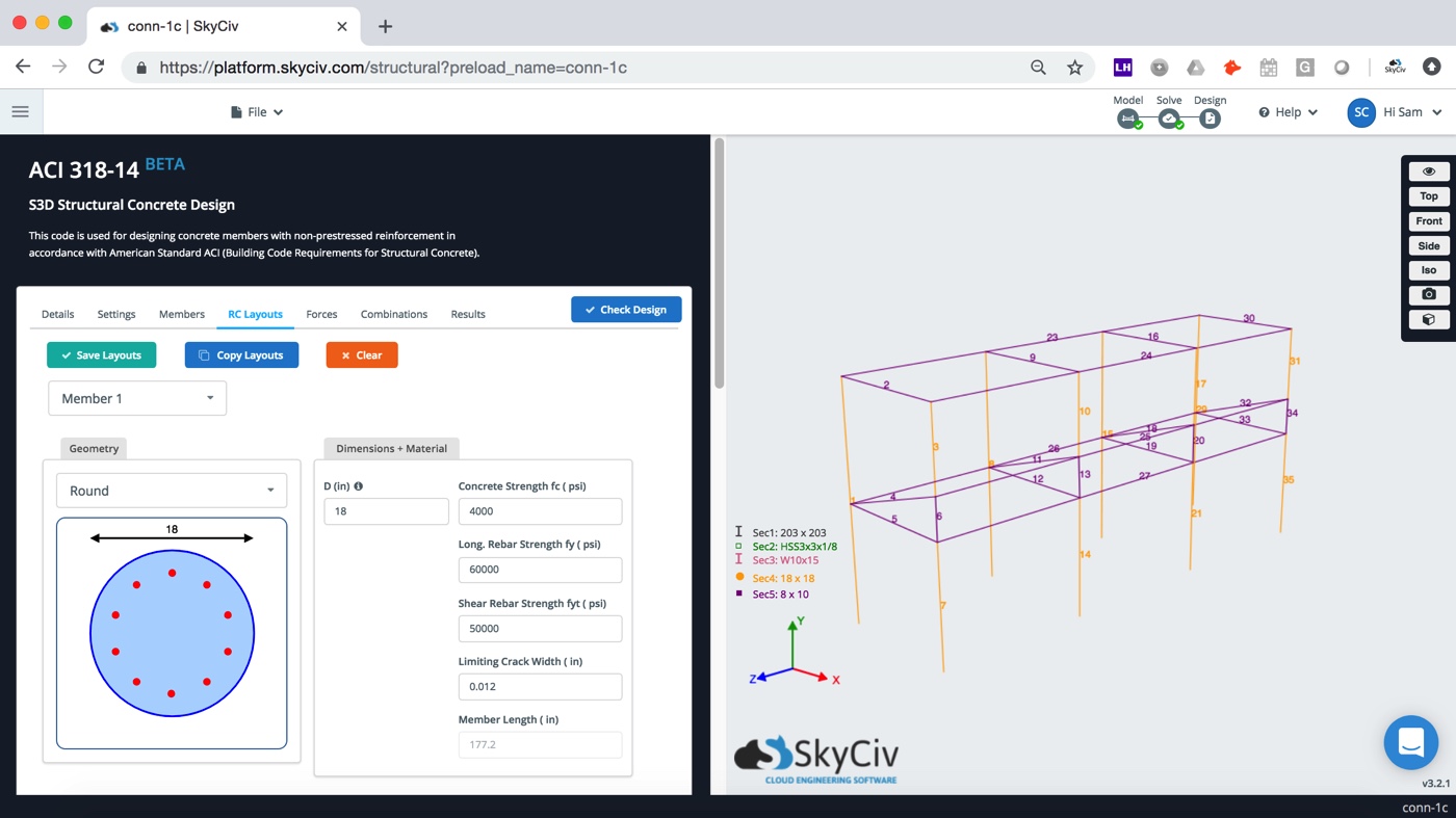
RC Layouts
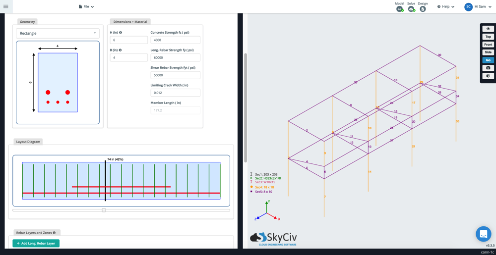
Basic information such as material properties and section shapes will automatically be pulled into the module. From this function of the module you tin also control the following:
- Define Longitudinal Reinforcement: add multiple layers of reinforcement (shown as red horizontal lines), including input for:
- Number of bars
- Bar Diameter
- Top/Bottom distance
- Cover
- Start/End points
- Shear Reinforcement:add multiple layers of shear reinforcement (shown in dark-green, vertical lines in the graphics)
- Number of bars
- Bar Diameter
- Spacing
- Start/End position
- Deflection Controls:Command limits and sustained live load percentages
[icon icon=info] Applying the aforementioned layout to multiple members
In the above example, y'all might want to apply the aforementioned reinforcement layout to all columns. You tin do this by using the blueCopy to Membersbutton. This volition allow you to re-create the rebar characteristics across multiple members.
Loads and Load Combinations
Results from the analysis are automatically imported from your analysis model, so at that place isn't much else required here by the user. Users can review the loads under theLoad tab, which will present all the bank check points and forcefulness diagrams (bending z, bending y, axial, shear y and shear z) which are all used in the design calculations.
Your load combinations are also included and imported from your model – if you did non add together any during the modelling stage, simply go back toModeland add load combinations, or import load combinations from ASCE, AS, EN or CSA design standards in S3D. You tin besides add transmission load combinations from within the RC design software.
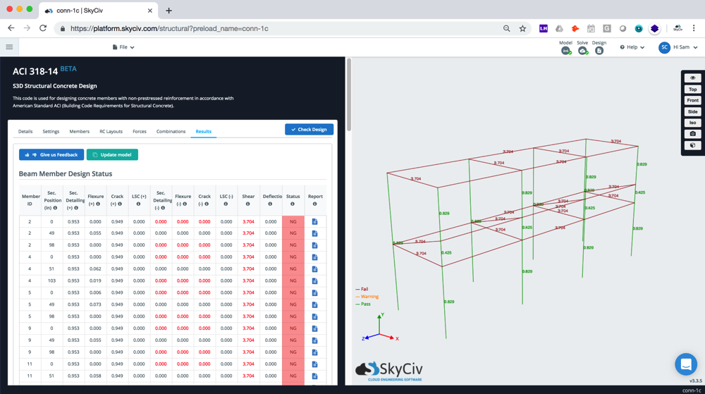
Results
Once yous're ready to run the design module, clickCheque Design.The results will exist displayed equally a table (columns = different checks and rows = the different members). Hover over the [mini-icon icon="info-sign"] for more than data about each of the pattern checks. On the right, the model will display a traffic-lite style result – with the governing ratio showing adjacent to the fellow member. In the beneath case it is evident that the columns are passing, but the beams are failing due to insufficient shear capacity, with a utility ratio of 3.704. This ratio is how much capacity of the fellow member is beingness utilized. It means the member is iii.7 times over capacity.
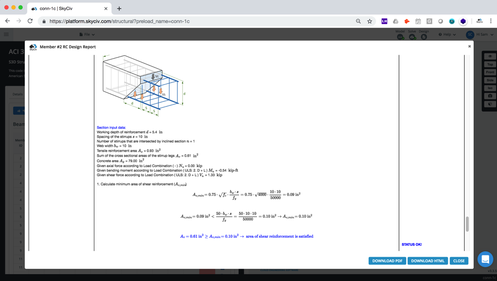
Detailed Calculation Reports
One time solved, you tin can as well review the total calculation reports which show the total pace-past-stride calculations performed by the software. Here's an instance ACI 318 calculation study produced by SkyCiv RC design software. This helps understanding the exact assumptions, references and criteria for the design checks. This tin be downloaded as a PDF to shop for your records or pass on to customer.

Source: https://skyciv.com/docs/skyciv-rc-design/general/beam-column-design-s3d/
Posted by: whartonteme1960.blogspot.com
0 Response to "How To Draw Beam And Column Layout"
Post a Comment